
As recalled by Roger Lindquist, August 2011
And edited by Jim Schneider, Marc Kacmarcik, Vince Rybel, Don Marske, and Susie Gaare, January, 2016
(Editor’s note: The following is a work in progress. The Alumni History editors thought it was important to share this near complete draft while we await further contributions.)
During 2011, Roger Lindquist was beginning to plan for full retirement after more than 55 years with CH2M HILL. He had worked at CH2M for most of the firm’s 65 years of existence, and his experiences spanned the era when geotechnical engineering was developed at CH2M. Roger has seen many changes in Civil and Geotechnical engineering during the past 55 years and, based on his memory, wanted to share his recollections of the development of geotechnical engineering at CH2M in this document. His original document was 66 pages in length. We have edited it down to its current length of 20 pages with the sincere hope that we have retained Roger’s original intent and voice.
Roger desires that this history remain in draft form to allow the CH2M Geotechnical Group the opportunity for both corrections and additions as they see appropriate to record the firm’s history of geotechnical engineering.
Introduction
Geotechnical engineering, also known as soil mechanics, is a relatively new discipline within civil engineering. The serious development of soil mechanics began in the 1930s based on the early work of Terzaghi in the 1920s. Thus, when the company started in 1945, soil mechanics was only beginning to be recognized as a serious discipline within civil engineering. And, it is only fitting that CH2M’s first official project was a “geotech” project.
Since that Project No. 1 over 70 years ago, there has been rapid development in geotechnical engineering, ranging from methods for field investigation, laboratory testing, analysis, and design. Calculators and computers have also accelerated our work. The purpose of this paper is to summarize and document the development of CH2M HILL’s geotechnical engineering people, tools, services, and projects.
Our People
Like the development of all the disciplines of the firm, it was the talent and character of the people that enabled the successful development of the geotechnical group. Over the years, we added several geotechnical engineers and later brought on geologists and, when necessary, contracted with several specialty firms. Following is a brief summary of the some of the individuals involved over the past 55 years.
The Geotechnical Group and Supporters
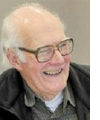
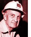 Jim Howland
Jim received his basic soil mechanics training at the Massachusetts Institute of Technology (MIT) in 1939 under Donald W. Taylor. With this education, plus his experience with the Standard Oil Company of California and in WWII as a construction officer in the U.S. Army Corps of Engineers, Jim had the best training in civil engineering and soil mechanics of the original CH2M partners. As the company grew, Jim gravitated to become the permanent managing partner and did less and less project work in the 1960s.
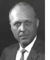 Holly Cornell
Holly was a technically strong structural engineer, who appreciated the problems of foundation design, earthquake forces, structural deformation, including prediction of and structural design for earthquake forces. He was a strong supporter of our early soils group.
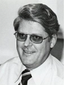
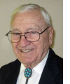 Bill Watters
With a 1951 degree in civil engineering, construction experience as a heavy equipment operator during WWII, and his great judgment, Bill was a Project Leader on major civil engineering and soil mechanics projects from 1952 until his retirement in 1985. Some of the major responsibilities included the Carmen Smith hydro, Boeing 747 pavement project, and managing design director for the Water and Sewage Authority (WASA) Caronia-Arena Water Supply Project for the government of Trinidad and Tobago
 Vaughn Sterling
Vaughn joined CH2M in 1957 and worked with Bill as a civil engineer and was part of the civil group that worked on dams, air fields, and pavement design. Vaughn became the company expert on airfield pavement design and construction in the 1970s to 1990s, retiring in 1993.
 Ken Stuart
Ken came to the firm in 1952 as a very experienced, talented, senior design technician. As a retired Seabee, plus his experience with light construction, he helped with survey, fieldwork, drafting, and design for all types of civil projects including dams, boat basins, and marinas. Ken became the lead designer of small boat harbors and marinas in the 1960s to 1990s. Ken retired in 1993.
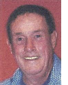
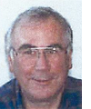
 Roger Lindquist
Roger graduated as a civil engineer from Oregon State College, now Oregon State University (OSU), in 1955. Because of his ‘1A’ draft status, the job market for him was very limited. A month after graduation, CH2M made the only offer for employment he received. That was only because CH2M had just been awarded a contract to help find a water supply for the Georgia Pacific Corp. (GP) for its first west coast paper mill to be located in Toledo, OR.
His initial task was to set up and monitor stream gauging stations on tributaries to the Yaquina River near Toledo, Oregon, to measure late-summer flow. This required making frequent field trips to the Coast Range west of Corvallis to set up measuring stations and collect the recorded water level data and to make stream flow/yield estimates. These data were used to evaluate water supply options for the proposed GP mill in Toledo.
In November 1955, while working for Earl Reynolds in Boise, Roger was drafted into the Army. He rejoined the firm in July 1958 after his Army duty and after 9 months at the University of Minnesota where he received a Master’s Degree in open-channel hydraulic engineering, with a minor in soil mechanics. He also had a part-time job with the U.S. Department of Agriculture (USDA) (Soil Conservation Service) constructing physical hydraulic models in the St. Anthony Falls Hydraulic Laboratory. He returned to Corvallis and his job with CH2M in the summer of 1958. Roger worked with Bill Watters, Vaughn Sterling, and Ken Stuart on dams, hydraulic structures, water supply intakes, outfalls, and general heavy civil engineering projects between 1958 and 2010.
 Larry Well
Larry started as a technician in 1959, after his military service with the Marine Corps. He did lots of fieldwork and established and operated our soils laboratory in the west end of the office building at 1600 Western Boulevard. He returned to OSU and obtained a degree in General Science, just lacking the summer field classes for a degree in Geology. Larry was very creative and inventive with the ability to solve problems in the soils lab and during field exploration. Larry also helped on construction and operation of several physical hydraulic models. In 1963, at the urging of our sanitary engineers, Bob Pailthorp in particular, he also started up the operation of the water and wastewater laboratory.
Jim Fuller
Jim graduated in forestry engineering from OSU and began working at CH2M in 1959 or 1960, after his military service. Jim had outstanding judgment for solving design and construction problems. Jim worked on most dams designed by CH2M until he retired. Jim had a wide-ranging curiosity and developed innovative solutions to our design projects.
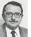 Ed Worth
Ed was the first real professional geotech the company hired (1964). Ed received his B.S. Degree in Civil Engineering from OSU, and his M.S. Degree in Civil Engineering from the University of Illinois. He also completed his class work for Ph.D. Degree in Civil Engineering (geotech) at Illinois, but did not complete his thesis because he had a large family and needed to start working to support them. Ed’s brother, Joe, was a senior engineer in the CH2M Water group for many years. Ed’s and Joe’s father was the County Engineer for Lane County for many years, and their grandfather was an early pioneer surveyor in Oregon.
The geotechnical section became much more professional with the hiring of Ed Worth in the late 1960s. Ed made strategic hires and was a great leader and a very bright geotechnical engineer. Ed’s premature death in 1976 was a great loss to the development of our geotechnical capabilities.
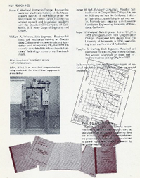
A sampling of our early highly trained geotechnical personnel, which formed the nucleus of the geotechnical staff for the next 40 to 50 years, include:

John Ramage, BSCE, Washington State University (1970), MSCE, University of Illinois (1971). John was hired by Ed Worth to be the first member of the geotechnical discipline to work in an office outside of Corvallis. When Ed was comfortable with John he turned him loose in Portland.
Larry Roth, MS, University of Wisconsin, had a big impact on the geotech group, serving as discipline director when we combined and integrated the geotechnical and groundwater groups.
Jim Schneider, MS, University of Missouri at Rolla
Jerry Tracy, MS, OSU
Dennis Marker, MS from University of Illinois. Enrolled at OSU, Ph.D. program. Dennis’ early death was also a great loss to the development of our geotechnical capabilities.
Joe Green-Heffren, MS, ????, was a key geotech in Denver for many years. Joe managed the Standley Lake project through design.
Vince Rybel, MS, University of Illinois
Ron Siegel. Purdue
Tom Huntsinger, Stanford
John Livingston, University of California at Davis
Rick Riker, Utah State
Ken Green, Utah State
Geologists
In the 1950s and 1960s we used several local OSU staff geologists to help on projects. As we recognized the value of geologists, we hired our own. Some of these early geologists included: Robin Nelson and his wife Sandra Stansbury, Alex Tula, Frank Pita; and Bonnie Witek
Doug Hanson was one of our first serious geologists. Doug came from his own company, LaShelle-Hanson, in 1982. Doug provided tunnel experience to the company for the Milwaukee project. Doug brought Dick Coon to the company to strengthen our tunnel design staff at the Milwaukee Office (MKE).
 Dick Coon also joined the firm in 1982 for the Milwaukee project. He worked for 27 years, concentrating first on the Milwaukee tunnel work and then the Lake Mead Water Supply projects for the City of Las Vegas. He served as manager of Underground Engineering Services before retiring in 2009. Dick passed away in 2010 after a short retirement.
Office Facilities, Staff Development, and Tools
We clearly were able to hire the geotechnical talent, but we also needed to house them and provide them with the training and tools to make them a cohesive and productive unit.
Office Facilities
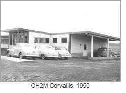
In 1950, the firm moved from their downtown 2nd floor office above the Albright and Raw Drug Store located on the NE corner of 3rd and Madison to their new office building at 1600 Western Boulevard. In this new one-story building, each of the initial partners, Holly Cornell, Jim Howland, Burke Hayes, and Fred Merryfield, and recent partners Archie Rice and Ralph Roderick, had small individual offices. The managing partner, Jim Howland, had a slightly larger office.
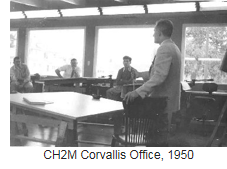
The staff were located in a large, open ground floor room, with the draftsmen standing at rows of drafting tables located on the north side (two abreast) and the engineers seated at desks on the south side, three abreast. Roger Lindquist sat between Bill Watters and Bob Adams.
Three people shared a single phone that would ring with a complex number of rings to identify the person for the call. A project number was necessary for all long-distance calls that were placed through Della (Hickey) Matthews at the reception/switchboard desk. There were no Xerox copiers until about 1964.
All typing was done by a typing pool from hand-written text or dictation. The only way to make copies was to use the blue line print machines until the early 1960s. All blue line copies had to be charged to individual project numbers. When Xerox machines became available in the early 1960s, each copy had to be recorded with a project number for billing. Polaroid cameras were a great help to record field information in the early 1960s, and film was charged to a project number.
In the 1950s and early 1960s, reports and contract documents were typed onto blue ditto masters. These were proofread with a team editor and any available draftsman or junior engineer.
Dress “code” was professional, with white shirt and tie strongly suggested.
The first expansion of this office began in the late summer of 1955, with a two-story wing extending south of the main building with Roger Lindquist setting the batter boards and grade stakes. The contractor, for all expansions, was Quinton Greenough. Greenough was a civil engineering classmate of the partners who played football for OSU including the January 1, 1942, Rose Bowl game, which was moved to the east coast because of the Pearl Harbor attack.
The office was enlarged several more times; each expansion provided more working space plus more private offices for senior staff. The office moved to the Walnut Avenue office in 1983 and to the Hewlett Packard facility in 2010.
Staff Development
Throughout the evolution of the geotechnical discipline, the group organized several meetings designed to develop their skills. Topics included dam design and construction, rock engineering, seismic engineering, and so on. The most significant one was the Dam Symposium in 1972, which really defined the nature of CH2M geotechnical meetings.
Tools
Each engineering discipline has its unique set of tools. Following are some of the tools used by our geotechnical engineers.
Reference Books
Soil mechanics analysis and design were based on work by Terzaghi, Casagrande, Peck, and others. Reference books available to and used by engineers in the late 1940s and 1950s, when CH2M was beginning, included:
Terzaghi and Peck – Soil Mechanics in Engineering Practice 1948
Taylor – Fundamentals of Soil Mechanics 1948
Lambe – Soil Testing for Engineers 1951
Anderson – Substructure Analysis and Design 1948
Peck, Hanson, and Thornburn – Foundation Engineering 1953
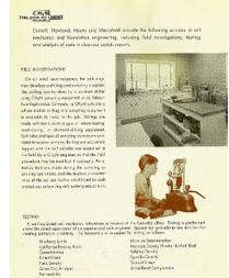
Field Exploration 1950s and 1960s
There were no drill rigs that specialized in field explorations in Oregon, until Pittsburgh Testing Laboratory moved a drill rig with Joe Stravinsky to Portland in about 1960 to support its testing laboratory. Joe was a great driller who taught all inspectors a lot about proper drilling and sampling methods in the early 1960s. Prior to that, we performed field exploration by various means such as the following.
Test Pits
We used rubber-tired backhoes to excavate pits to a depth of about 16 feet and sometimes used large crawler-mounted backhoes to reach a depth of 25 feet. Logging was frequently done by riding in the bucket down to the bottom of the pit, cutting bag samples from the side of the pit. A pocket penetrometer was used to estimate soil strength by pushing it into the sides of the pits. A Torvane was used later to estimate shear strength. We also used the backhoe bucket to push Shelby tubes into the formation and then the backhoe would dig out the tube.
Hand Auger-Drilling and Sampling
For light-weight buildings, most of our explorations to a depth of 15 to 20 feet (sometimes 25 feet) were made by using 4-inch-diameter hand augers as long as there were no gravel particles in the soil and above the water table or limited inflow of water.
We had several “kits” with auger, handle, 3/4-inch pipe extensions (about 30 inches long), pipe wrenches, drive head and 30- and/or 60-pound driving weights, and hydraulic jacks. This was normally a one-person job for shallow borings; but, for most jobs, a two-person crew was used. The drive weight was lifted manually 30 inches and dropped on a section of a rod with a welded driving plate. Pulling the samples was a gradual process with each person lifting up on a pipe wrench, while walking around and around, pulling up on the drill rod, and gradually lifting up until the sample was free. High groundwater increased the problem and difficulty of sample recovery.
Churn Drill-Type Well Drilling Equipment
This type of equipment was used to drill test borings deeper than 20 or 30 feet. Holes were drilled to the selected layers of interest (or at 5-foot intervals) using a weighted bit suspended from a cable that was raised and dropped repeatedly to advance the hole. When the hole reached the next sample depth, the rig used threaded drill rod equipped with a split spoon or a Shelby tubes to push or drive the sampler down to obtain samples.
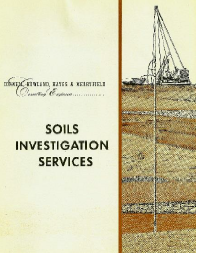
SECO
In about 1955, CH2M formed SECO (Soil Exploration Company) when CH2M bought a small skid-mounted Acher Drill Rig. We printed brochures to advertise this independent company. This rig was hauled on a trailer, which was pulled behind a red 1950 Chevrolet van filled with tools.
The rig was used on projects where borings were deeper than about 20 feet or where boring with a hand auger was difficult. A crew of two or three was needed to operate this drill, and production was slow. This rig was used for soils investigations for several dam projects, and high-lined across canyons to drill both abutments. It was not a successful company; and, as soon as better equipment was available from contract drillers, the rig was given away to a logger.
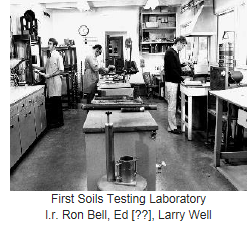
Soil Testing Laboratory
Larry Well set up the soil testing laboratory in the carport located on the west end of the 1600 Western Boulevard Office in the early 1960s. He was assisted with technical help from Jim Bell, (OSU Professor) and with internal support from Jim Howland, Burke Hayes, and Bill Watters.
The first consolidation machines used scissor jacks to load the samples and bathroom scales to measure the load on the sample. Soiltest, Inc. of Chicago was the only supplier of mass-produced, relatively low-cost soil testing equipment at that time. Generally, Soil Test provided poor equipment and even poorer service. Initially, we used one of their direct-shear machines. It worked fairly well and provided the soil-strength information for most of our simple projects.
Later, we bought a triaxial testing machine from Soiltest. Larry was able to make basic shear tests, but the Soil Test equipment had limited ability to measure pore pressure. Membranes were made of rather heavy rubber and often had leaks.
The last project where we used the direct-shear testing machine was during the design of Senac (Aurora) Dam, in about 1983 with Ralph Wilson, Joe Green-Heffren, and Joe Cesare. Joe was hired by Ed Worth in CVO, transferred to RDD and then to DEN where he eventually left the firm to start his own successful geotechnical consulting business.
The Corvallis Lab was closed when we moved from 1600 SW Western Boulevard to the Walnut building in 1983. The equipment was sent to Portland where we set up a very nice lab at 5221 SW Corbett Avenue, about 2 miles south of the Portland office. In about 1990, the entire laboratory operation was moved to Denver. A few years later, the Denver office was relocated, and we made the economic and technical decision to stop doing our own lab work as there were several excellent contract labs available, and we no longer felt it was necessary to do our own testing to get the quality we needed. Since then, we have been using commercial soils laboratories on a contract basis in each city where we do geotechnical engineering design.
Analyses
were Taylor, Terzahgi, Terzahgi and Peck, and Lambe. Areas on drawings were determined by a planimeter, and calculations were made with a slide rule or the hand-operated Marchant calculator. The HP 35 pocket calculator became available for about $400 in about 1973 or 1974. In those early years, only one was available for sharing in each department.
An early computer program for slope stability was developed by Ron Siegel for his Master’s Degree thesis at Purdue in the late 1970s. He brought this program with him to Corvallis where it was made available commercially. It was not particularly successful because it could not compete with other programs developed by full-time programmers.
Services
Early Reports
In the 1950s, reports were hand typed on the blue ditto masters and proofread (out loud) with a secretary and anyone short of work. Figures for reports were all hand drawn by Swede Nordquist or other drafting techs and reproduced on the blue-line machine. CH2M printed and bound reports in the print room by the Hickey brothers.
For major project presentations in the 1950s and 1960s, the presentation graphics were hand drawn on window shades, supported on an easel, and pulled down at the appropriate time during a presentation. Burke Hayes made excellent public presentations.
Construction Observations
The primary construction service of the geotechs has been the field testing for construction control for compaction. The art of testing embankments for compaction density has evolved over the years.
Initially, we used a 1/30th-cubic-foot cylinder (sharpened on the bottom edge) that was pushed into the embankment by the blade of a bull dozer (from a preleveled surface). The sample was weighed and moisture content determined by drying the sample in a kitchen range oven, frequently in the tourist motel where the engineer was staying.
The next equipment for field density testing was a volumetric device using water, with a calibrated, vertical glass cylinder in a metal tube, and a balloon set onto a base plate. The compacted soil surface was leveled and the base plate nailed down. The tare volume was determined by pumping the balloon with water to fill the space between the base plate and the soil. A hole was then dug through the base plate into the underlying soil with the cuttings put into a can. When the hole was big enough (about 1/30-cubic foot), the moist soil was weighed. Thus, we had the wet density; and, by drying a sample of the soil, we would have the moisture content and could obtain the dry density to compare with the specifications. View early marketing brochure (PDF) of the firm’s Soils Investigative Services.
 Nuclear gauge was fast and easy to use, but it required lots of red tape to keep up the license for the tiny amount of radioactive material used in the probe. Larry Well had to continually fill out forms for this equipment for the Atomic Energy Commission.
Significant Geotechnical Projects
1955-1960
Georgia Pacific
GP started evaluating a potential paper mill site at Toledo, Oregon, in the summer of 1955. As mentioned previously, this was the reason Roger Lindquist was hired, to help with the fieldwork necessary to find a water supply for the proposed mill. He set up stream gauging sites in the coastal streams southeast of Toledo, and made frequent trips to the area to measure the flow in the streams with a current meter and to collect the water-level gauge data. We used the rural postal man to read staff gauges.
The early conclusions were that the Yaquina River watershed could not provide a dependable source of surface flow even with a large storage reservoir. This led the search for water to the Siletz River, which was quickly recognized as the only reliable source of water in the area. This source was north of Toledo and would require a pump station on the Siletz River to pump water over the ridge and fill a reservoir in the Yaquina drainage system near Toledo during the winter. Water was released from the dam to flow down the creek to a saltwater barrier across a branch of the Yaquina Bay so the fresh water could be pumped to the mill before being contaminated with salt water. The storage reservoir would have capacity to provide water for the proposed mill during the dry summer and fall months. Thus, the Olallie Dam, a 50-foot-high earth dam with grouted foundation, near Toledo, Oregon, designed by Bill Watters and Vaughn Sterling in about 1957, became CH2M’s first significant dam project.
The dam developed significant leakage through the abutments during the first filling. This flow of seepage water was greatly reduced by yo-yoing a sheepsfoot roller up and down the abutment slopes, while the reservoir was full of water. Fine-grained clayey silt soil was also dumped down the slopes during this operation. The dam was raised two times in the 1960s and 1970s and is still in use in 2010. It has been inspected annually by CH2M HILL staff since construction.
Bill Watters, Ken Stuart, Vaughn Sterling, and many others worked on the GP project (about 1956-1960) that also included long pipelines, pump stations, an ocean outfall, plus pile foundations for the mill buildings. It was on this project that CH2M learned that, during the Ice Ages, when a vast volume of the planet’s water was tied up in glaciers, the water level in the oceans receded; and the Pacific Ocean shore line was many miles west of Newport. During this time, the river valleys were eroded, forming the original river bed of the Yaqunia River about 100 feet below the level of the present river valley. As the glaciers melted and the ocean level rose, the river valleys filled with soft sediment, making pile foundations necessary for any heavily loaded foundation. We found this to be applicable to all rivers on the Oregon and Washington coast, and any development in these river valleys required deep pile foundations.
Big Creek Dam
Big Creek Dam No. 1 was a low earth dam for water supply designed by Jim Howland for the City of Newport, Oregon. The dam was built about 1950 and has been raised one or two times since. The outlet was a corrugated metal pipe (CMP).
Menasha Paper Mill Development (1959 to 1970)
This project included the design and construction of a causeway across the north arm of Coos Bay to provide access to the proposed Menasha Paper Mill, which was to be located on the North Spit.
Field exploration for the causeway was made with test pits excavated by one of the crane barges of Umpqua River Navigation. The work included the development of the Mill Site on the North Spit. We moved the CH2M drill rig over the dunes by using a Pacific Power dune buggy (truck). The exploration indicated the deep deposits of sand were too loose to provide the support of the heavy, vibrating paper machines. To provide a suitable foundation for the building and equipment, the deep deposits of sand were compacted by using the vibroflotation process to compact the sand so the buildings and paper machines could be supported on spread footings.
Archie Rice designed an effluent treatment/seepage lagoon near the beach about 2 miles west of the mill. This lagoon seeped (leaked) as designed for a few years, but gradually became plugged with sludge, requiring the design of an ocean outfall. Larry Well, Joe Scott, and Roger Lindquist made the field surveys and ocean studies and preliminary design of the outfall that was to extend about 4,500 feet into the ocean and then discharge through a diffuser parallel to the shoreline. The construction was to be made using the bottom pull technique that the Fred Devine Diving & Salvage Company had used on other outfalls on the Northern California and Oregon coast. Joe and Larry worked with a diver to make jet probes into the sea bed, and flew over the site in a small airplane dropping drift cards to monitor the currents.
Gary Graham designed the diffuser, based on his class work at the University of Washington. To prevent “wave pumping” of ocean water and sediment into the diffuser ports, check valves were installed on the diffuser ports. This was the first diffuser that we know of that was fitted with check valves. This started a new concept, and Red Valve developed noncorrosive rubber check valves especially for diffuser ports. Currently, almost all ocean outfalls are equipped with check valves.
The 4,500-foot-long outfall pipe consisted of concrete-coated, mortar-lined, welded steel pipe assembled on a narrow-gauge railroad perpendicular to the beach where the joints were welded. Excavation of the trench was made with the prop wash of Devine’s renowned M/V Salvage Chief. The pipe was pulled into place in about 24 hours during a low tide in late September, 1961 or 1962. The wye diffuser arms were hinged to the main pipe and folded back during the pull, and later unfolded to their wye shape. Because the discharge permit required no discharge during the late summer and early fall, the Menasha outfall was to operate seasonally.
Albertson Food Markets and Safeway Stores
During the 1960s, we conducted foundation studies for many of these one-story buildings throughout western Oregon and Washington plus a few east of the Cascades.
Architectural Support
Most of this type of work was for projects developed by Wayne Phillips through his contact with his architectural clients. Wayne provided mechanical and electrical design services for several architects, especially with Jim Payne, AIA in Salem. These buildings included many schools, offices, hospitals, and commercial buildings in western Oregon and on the coast. The first one of these projects that Roger worked on was in 1955 with a University of Oregon student, Oscar Frial, for a school site at Powers, Oregon. After graduation, Oscar became CH2M’s first full-time architect.
Wastewater Treatment Lagoons
Large, shallow, aerated or nonaerated treatment lagoons were a very popular means of economical treatment for both industrial waste and domestic sewage in the 1950s and 1960s. These shallow lagoons required relatively tight soil bottoms to reduce seepage with low dikes to contain the effluent with a liquid depth of about 5 to10 feet. Originally, these were aerated by natural wind waves. Later, floating aerators were installed. Treatment lagoons were constructed at Klamath Falls, Ontario, LaGrande, and Baker for treatment of wastewater from paper mills, canneries, and domestic sewage. In the 1960s, plastic liners became available to reduce seepage through the pond bottom. One of the first large liners in the U.S. was for the Weyerhaeuser Corp. at their Springfield, Oregon, paper mill.
Log Ponds
Most saw mills in the northwest floated their large old-growth logs in shallow lagoons, for easy handling to move them from the log dump to the saw mill. We furnished design for these mill ponds.
Later, logs were moved to log yards with huge rubber-tired equipment; and CH2M designed heavy-duty pavement for these log yards. To measure deflection of the pavement under loaded conditions, we used a modified Benkelman beam. The length of the lever arm was extended twice the normal length (or more as necessary) for accurate deflection estimate. This same device was also used for measuring deflection of airport pavement, using a Boeing 707 loaned by Pan Am to provide realistic loading.
Carmen Smith Hydro Project
Burke Hayes and Bill Watters worked closely with the Eugene Water and Electric Board (EWEB) on the development of the project concepts and permitting in the late 1950s and early 1960s. However, to obtain funding, the design had to be done by an experienced, large engineering company; so EWEB retained Bechtel to provide the final design, with CH2M doing very limited final design work on the project.
Circular Prestressed Concrete Reservoirs
The structural group began the design of these types of reservoirs for treated water in the early 1960s. The geotechnical group provided soils exploration for the reservoirs of Eugene, Corvallis, Gresham, and McMinnville. Most of the foundation exploration was done using the client’s backhoe equipment.
Airfield Pavement
The first major airfield pavement project was the Kingsley Naval Air Field at Klamath Falls. Reconstruction of these WWII runways and taxiways had been designed and constructed but were showing premature failure. The Navy contracted CH2M to evaluate why they were failing. Ken Stuart made the initial field investigation, and Roger Lindquist worked in the field and in the laboratory with the samples of the subgrade and subbase. Roger, who had recently studied at the University of Minnesota, minored in soil mechanics taught by a world-class expert in pavement design where the pavement was exposed to deep frost conditions. With this background, Roger suspected that the rapid failure of the new pavement at Kinglsey Field was probably caused by frost damage to the subgrade. This was verified by some quick lab tests, and the pavement was redesigned to have a thick layer of expensive sub-base and base material that was not susceptible to frost damage. The Navy choked on the price but followed our recommendations, and the pavement has performed well for 50 year.
Boeing Apron for 747’s Manufacturing Facilities
Bill Watters and Vaughn Sterling moved to the Seattle area to head up the design of the heavy-duty pavement for Boeing’s 747 factories at Everett, north of Seattle, in the mid-1960s. Corvallis provided field exploration and laboratory testing as well as analysis for the design of the heavy-duty pavement necessary to support the 747 aircraft.
1960s
The most significant of the firm’s projects during this era were the development of the use of a water filtration process to treat secondary treated wastewater for disposal in sensitive areas. The Lake Tahoe Advanced Wastewater Treatment Plant was a major milestone that projected CH2M onto the pages of the New York Times, Los Angeles Times, Denver Post, and Reader’s Digest (PDF); and we instantly became a nationwide firm.
Indian Valley Dam, Northern CA
Indian Valley was a high (200 feet) earth fill dam with gated spillway, under design by Clair Hill & Associates (CAHA), when the companies merged. CAHA did most of the hydraulic design, with the dam design done by a company from San Francisco.
Hydro Electric Addition to Kingsley Dam, Nebraska
Constructed in the 1970s, a hydraulic model study of the outlet and diversion was conducted during construction by Larry Well and Roger Lindquist. The study verified that a large air vent was necessary for the temporary bypass flow of several thousand cubic feet per second.
Water Supply for Trinidad and Tobago, Arena Dam
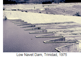
This project essentially doubled the water supply for the Republic of Trinidad and Tobago, West Indies, and included a dam, water treatment plant, reservoirs, distribution pipelines, and miscellaneous related work. The dam was notable because it was to be 100 feet high and located near the El Pilar Fault, with seismic risk comparable to the San Andreas Fault. Another problem was the presence of so-called “dispersive” clays, which could erode like fine sand or silt unless protected by proper design. Recent work by the Soil Conservation Service on dispersive clays and articles on this subject by Jim Sherard helped Jim Schneider and Roger Lindquist identify the potential for this problem at the Arena Dam site. Jim Sherard was a major outside consultant on this project. Jim Schneider and Roger Lindquist had the good fortune to travel with Sherard between Miami and Port of Spain, Trinidad, and had a 4-hour private geotech session with one of the greatest geotech professionals of all times. Jim Sherard’s visit to the project site verified the dispersive clay concerns, and major changes to the conceptual design were made. These modifications changed the design to provide a dispersive clay core with graded sand filters and sand embankments on each side of the core. The photo to the right is of the Low Navet Dam in Trinidad, 1975.
Raise of Rickreall Dam
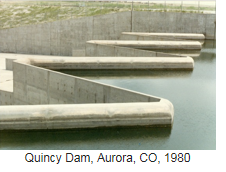
To raise the dam and increase the spillway capacity of Rickreall, Roger Lindquist designed and built a physical model for testing of the labyrinth weir spillway for the raise of Rickreall Dam. This project led to the design of many labyrinth spillways by CH2M including the Quincy Dam, in the Denver area, which caught the eye of the U.S. Bureau of Reclamation (USBR) designers, who began using the labyrinth spillway design for some of their major projects. Following the USBR model testing and use of a labyrinth weir spillway on one of their major projects (Ute Dam), they became widely used on many major projects worldwide. On the left is a photo of the Quincy Dam weir, 1980.
Breakwaters and Jetties
Jim Howland was a good friend of Howard Hinsdale/Umpqua River Navigation Company. We worked with Howard on the design of breakwaters and jetties. This work included working on development of quarry sites with close access to the Columbia River that could produce the huge, sound rocks for the jetties, and also be moved to the barge quay for transport to the jetty locations on the Pacific Coast.
OSU Wave Tank
Howard Hinsdale came to Corvallis to meet with the OSU Civil Engineering head and Jim Howland regarding the donation of a wave tank. During that meeting, Howard said he would construct a wave tank that was large enough to test jetty stones under heavy wave condition if CH2M would donate the design and manage the construction. This surprised Jim, but he responded and agreed to make the donation. That was the beginning of the world-class wave testing facility at Oregon State.
1970s
Upper Occoquan Service Authority (UOSA)
The Upper Occoquan Advanced Wastewater Treatment Plant, known by some as Tahoe East, was spawned by the Lake Tahoe project. The treatment facilities, located just south of Washington D.C., included a storage dam and many earth basins. After four decades from the formation of UOSA, CH2M HILL remains (2013) its prime design consultant, a position built on mutual trust, respect, and a common understanding of the goals UOSA works to achieve.
WASA Trinidad and Tobago
This water supply project included a major dam with major earthquake potential. Recent work by the Soil Conservation Service on dispersive clays and articles on this subject by Jim Sherard helped Jim Schneider and Roger Lindquist identify the potential problem of these materials at the Arena Dam site. Jim Sherard’s visit to the project site verified these concerns, and major changes to the conceptual design were made. These modifications changed the design to provide a dispersive clay core with graded sand filters and sand embankments on each side of the core. The photo to the right is of the Low Novet Dam in Trinidad, 1975.
Madison Metropolitan Sanitary District Sludge Lagoons
While preparing a Facilities Plan for the Madison Metropolitan Sanitary District (MMSD) (1975), the dikes surrounding a 130-acre sludge lagoon started to show imminent signs of failure. They had failed twice previously in 1970 and 1973. If they failed, digested sludge and supernatant would be discharged to Nine Springs Creek, a sensitive trout stream. The lagoons were founded on a marsh with very weak soils (peat bog).
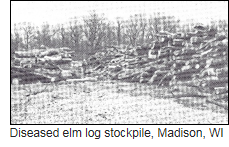
After reviewing alternatives, including the use of steel sheet cutoff walls that ranged in cost to upwards of $10 million, Larry Roth came up with the idea of using Madison’s large stockpile of diseased elm logs to provide a lightweight embankment material. This mixture of chipped elm logs and conventional granular backfill would be installed over an engineered mesh fabric (a baggie), allowing the embankment to initially sink and then “float” on the existing dike. The estimated cost to perform the embankment stabilization was $650,000. The proposal was accepted, and Jim Schneider conducted the final design and construction inspection. The Wisconsin State Highway Department was so intrigued with the project that it sent crews to videotape the construction. Settlement monuments installed in the dike verified projected settlement. The dikes continue to perform today (2010) with no signs of failure.
Bull Run Hydro
This project added hydroelectric capacity to Portland’s water supply facilities at Bull Run. The design utilized retired Corps of Engineers staff. Vince Rybel and Dennis Marker played a key role in this difficult project.
Gem State Hydro
This was our first major hydroelectric project with a large dam across the Snake River at Idaho Falls. We encountered difficult foundation conditions and erosive soils. Jim Sherard was our outside consultant on this project.
Weyerhaeuser Company Treatment Lagoon, Springfield, OR
This was the first major polyvinyl chloride (PVC)-lined treatment pond. The liner manufacturer used this project in its ads in major trade magazines.
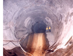
Milwaukee Water Pollution Abatement Program
The Milwaukee project was the first really big program management assignment for CH2M HILL. The scope of the assignment included collection, treatment, effluent reuse and disposal, and sludge stabilization and disposal (Milorganite). Clearly, the major portion of the project consisted of deep tunnels to store peak stormwater runoff that flooded the combined sewers and both spilled and to surface water, and overloaded the treatment plant.
CH2M HILL provided many geotechnical engineers for the studies, design, and construction for this huge project. Most of the geotechs employed by CH2M HILL at that time were involved with this project, some for 10 or more years. Many transferred to the Milwaukee office.
The project was similar to the just-completed Chicago system (designed by Harza), which was designed and constructed a few years before Milwaukee. The Chicago system had straight drop shafts to lower the combined sewage to the deep storage tunnels, which required large defoaming tunnels and vents that were generally not very effective. During the preparation of the proposal for the hydraulic model studies for the drop shafts necessary for the Milwaukee deep sewer storage project, Roger Lindquist insisted that the model study evaluate vortex drop shafts. The modeler of the San Diego vortex shaft had moved to the University of Iowa and was awarded the modeling of drop shafts for the Milwaukee project. This study provided excellent tools for the design of vortex drop shafts. Since that time, vortex drop shafts have been used almost exclusively; and no Chicago type of drop shafts have been constructed since the Milwaukee project.
1980s
Alexandria, Egypt
This project provided the opportunity to construct sewers, pump stations, and treatment plants for a large existing city with a huge portion of the population that was without sewers or sewage treatment. The area being rapidly developed was near sea level, with 50 feet or more of very soft unconsolidated soil that was continuing to consolidate under its own weight. Sewers were installed by pipe jacking methods. George Tamaro (TAMS), as outside consultant to the joint venture of CH2M HILL and Metcalf and Eddy, made several trips to Alexandria to help on this project. Again, many of the CH2M HILL geotech staff were involved with this project.
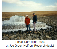
Senac Dam, Aurora, CO
CH2M HILL’s first major embankment dam in Colorado was a 130-foot-high dam containing 6.5 million cubic yards of compacted earth fill. It was constructed on a weak claystone foundation. This was an “off channel reservoir,” to be filled with water piped in from the Rocky Mountains. Soil cement (then a relatively new technique) was used for wave protection because hauling riprap out to the plains site was expensive. The soil cement facing is still in good condition as of 2012. On the right is a photo of filling of the dam in 1989.
1990s
Lake Travis Intake, Austin, TX
Using our outfall experience, a method of constructing an intake shaft in the Reservoir, followed by tunneling beside the vertical shaft, grouting the area, and finally connecting the vertical shaft to the horizontal tunnel was designed, bid, but never built. Rick Riker was design manager and lived in Austin during this design.
Iron Mountain Mine
This Superfund Site located near our office in Redding, CA, became a 20+-year cleanup. This project was led by John Spitzley/RDD and supported by many staff, including Jim Schneider and Roger Lindquist. The acid mine drainage was very acidic, with a negative pH, the strongest acid ever found in nature. This project won several major awards.
Lake Mead Intake
This project was won, in part, by a cartoon video illustrating how this intake could be constructed, with the intake riser being precast on shore, while the Saddle Island access shaft and tunnel were being constructed, and the riser shaft was excavated. As soon as the excavation was completed, the cartoon illustrated how the intake was floated to the east side of Saddle Island and sunk into the excavation and grouted into place, and the tunnel arriving below the shaft and the connection made in the dry. This was essentially how the project was designed and constructed. Again, many of the company geotechs were involved in this project.
Later phases of water studies, design and construction for Lake Mead intakes and tunnels continued to involve many of the company’s geotechnical engineers for several decades.
2000s
Standley Lake Dam Improvements, Westminster, Aurora, CO
Standley Lake Dam was originally constructed in 1909 for irrigation water supply. It was built by dumping earth fill from two parallel 30-foot-high railroad trestles (one upstream and one downstream) and filling the “canyon” in between with a mixture of water and clay to form a “puddle clay core.” The timber trestles were left buried in the dam fill, and the process was repeated to bring the total dam height to 100 feet. The dam failed shortly after completion – the upstream and downstream faces slumped 20 or 30 feet, undoubtedly due to the uncompacted fill. It was operated at a lower height until 1967, when it was stabilized by adding a downstream compacted soil fill stabilization berm and compacted fill to the dam top to return it to its original height of 100 feet.
Despite the 1967 stabilization work, the dam continued to settle, and the base continued to spread, stretching the cast-iron outlet conduits at the base of the dam and causing leakage at the separating joints. CH2M was engaged to finally stabilize the dam, enlarge the spillway to modern standards, and completely replace the old outlet works. The most notable geotechnical feature included two 72-inch-diameter “hot taps” of the full reservoir at depths of 60 and 90 feet using a design developed by Roger Lindquist. The outlet works included a 100-foot-deep, 30-foot-diameter shaft from which the outlet taps were launched, and a 700-foot-long tunnel to convey water from the shaft bottom to the downstream toe of the dam.
Other features included a large downstream stabilization berm, new valve house, interconnections to existing pipelines, constructed wetlands, and pumping the old outlet conduits full of concrete against full reservoir head, a method suggested by Jim Schneider. We had concrete arriving on site starting at about 3 AM to avoid traffic delays, and each conduit was filled with 250 cubic yards of concrete by continuously pumping from the downstream end over a period of about 3 hours. This project received an ACEC national award for engineering excellence.
Summary
The design of a project is not completed until the structure is built and in successful operation. Likewise, the design of a project cannot start until the geotechnical engineering is complete. Unlike most engineering disciplines, geotechnical engineering requires understanding of natural earth formations, natural processes, using and living with onsite material, and how our project will affect the earth at our construction site. Geotechnical engineering is related to topography, geology, hydrology, weather, climate, as well as adjacent manmade features. At best, geotechnical engineering is an inexact science, but it is based on observations and judgment developed through years of experience.
At CH2M HILL, our geotechnical studies and designs depend on the conditions that occur in nature; and we can never completely identify and define all of the existing conditions that exist at each site. Therefore, to arrive at the best definition allowable, work is frequently performed in stages. The work starts with the preliminary site visit where the topography, geology, and limited test pits are developed. This information is used to develop and complete a geological and geotechnical program including test pits, widely spaced borings, and detailed testing. The results of the geotechnical program are then incorporated into a final geotechnical report of design data and recommendations.
Budgets, in almost all cases, are not sufficient for adequate observations to fully evaluate a site generally allowing for only a few widely spaced borings and collecting samples at intervals of several feet. Conditions between borings and between sample depths, therefore, must be estimated by interpolation using the inexact science of geology and geotechnical judgment. And again, unlike most engineering professions, there are no codes to rely on. Therefore, to produce a sound geotechnical design report, the use of good judgment and common sense is critical.
Judgment is developed from a background of education, experience, an understanding of the natural process, and discussion with peers. One of the most important steps in the development of a successful career in geotechnical engineering is to work on several projects from concept development to studies, investigations, preliminary design, final design, construction observation, and successful startup. Working in the field during construction of an earthwork project is critical to the development of a sound geotechnical engineering group. Because of the need for reliance on experience, observations, and judgment, we have also found it invaluable to have several geotechnical professionals working together in an office, rather than located as a single isolated person in each office. A group of geotechnical staff, working together, communicating, and exchanging ideas on a daily basis provides the best atmosphere for developing a successful geotechnical support group capable of identifying and solving critical issues.
The foregoing concepts were applicable to several related projects frequently designed by our early geotechnical engineers, such as water intakes on rivers, reservoirs, or oceans; and outfalls into rivers and oceans. They are even more applicable and critical to the successful design and performance of the wide range of high-risk projects the firm is currently engaged in.
This brief summary of the development of geotechnical engineering at CH2M HILL is based on the experience of several of the geotechnical staff, each who have worked at CH2M HILL for many years.