
Flomatcher – A Variable Speed Pumping System
(Submitted by Carl Ryden)
Early on, Burke Hayes and Ralph Roderick saw a need to improve sewage pumping technology to conserve construction costs and reduce odors at pumping stations. Generally, the sewage was collected in a “wet-well” and the pumps would cycle on and off as required by the action of a float switch. During low flows, however, the sewage could stand for hours before well levels directed the pump to operate. This caused them to become septic and generate objectionable odors.
Burke conceived a design using a wound-rotor to drive the pump, controlled by a rheostat immersed in the sewage as an electrolyte. The motor speed could then be controlled to run the pump at a variable speed which would exactly match the sewage flow into the wet-well. The size of the wet-well could then be reduced to smaller dimensions and the sewage would flow continuously and remain “fresh,” thus reducing or eliminating the odor problem. The system worked very well and it was used on many subsequent plant designs, many of which are still operating today. This was the original model of the Flomatcher system and was called Flomatcher Model A.
Ralph, however, was not completely satisfied. The water rheostat took up too much room and it was difficult to keep clean. “Why can’t we translate the sewage level to a remote speed controller at ground level and cut down on construction costs still more?” he asked. A simple low pressure air bubbler system, immersed in the small wet-well and piped up to what could be described as large manometer structure, was developed. The air pressure from the bubbler tube caused a differential level in the “manometer” on the main floor which reflected exactly the sewage level in the wet-well. A rheostat was designed to use the level change in the manometer cabinet to vary the speed of the pump motor. An electrolyte was used in the manometer cabinet that was more concentrated than sewage so the control components could be more compact. This device was called Flomatcher Model B.
A third model, called Flomatcher Model C was subsequently designed to control a booster pump application in a water transmission line to maintain a downstream pressure at a preset level.
During the development of these pump control systems, the City of Corvallis generously permitted CH2M to install experimental models into their existing systems to fine-tune the design process. This was a very helpful gesture on its part and CH2M was extremely grateful for their willing and cooperative spirit. The Flomatcher got a lot of attention for CH2M and opened the door to many new projects. A separate company, General Service Corporation was set up to market the pump control systems.
The following is an excerpt from the Application Description as printed in the original GENERAL SERVICES COMPANY Sales Bulletin:
Flomatcher Operation
“The Flomatcher self regulated variable speed pumping system utilizes a wound rotor, induction type electric motor to drive a centrifugal, mixed-flow, or propeller type pump and is used where sewage or water flows to the inlet valve at a varying rate. The inlet to the pipe is arranged in the sewer channel or water channel. The speed of the motor is regulated by a liquid rheostat connected across the secondary windings of the motor, and the liquid rheostat is positioned physically with respect to the liquid flow channel so that the level of the water in the rheostat and consequently its resistance is directly controlled by the liquid level in the channel. The rheostat is designed so that the speed of the motor is such that the discharge rate of the pump is at all times equal to the liquid inflow in the channel.”
The Flomatcher Operating System
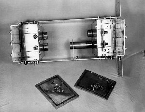
A Component of the Flomatcher System